Week 12, July 18th – 24th:
The mower is able to cut the grass as it moves forward, but because moving forward requires a minimum amount of speed to overcome the friction of the grass and the treads, the mower ends up moving too fast to give the blade a chance to cut the grass below it. Ideally, the mower would be moving forward slowly so that the blade can spend a good amount of time over each patch of grass to ensure it is cut, but moving slowly forward is unfortunately not an option. The mower can only move forward at full speed or not at all.
The video below shows the functionality of the mower to send an email notification to the user if it gets stuck for too long. For the demo video the code was set to send the email after 10 seconds of being stuck but in the final code, the mower will wait 20 minutes before sending the user the email to give the mower a chance to require the RTK lock. The email gives the user 10 minutes to move the mower before the system shuts down automatically after the stuck timer reaches 30 minutes.
As expected the mower has no trouble moving forward through the grass, although it does tend to turn slightly when moving forward. This is likely though to one of the motors being slightly weaker than the other. While moving forward proves to be no issue for the mower, the system does struggle when it comes time to turn. The first video below shows one example of a successful turn while the second video shows what happens when the mower can’t overcome the friction of the grass. This is mostly due to the quality of motors and tracks on the mower. If the motors could be replaced with something with a little more power then it would likely have no trouble turning on grass.
Week 11, July 11th – 17th:
Return home procedure successfully brings the mower back to the docking station and shuts down automatically. Only issue is that RTK cm accuracy isn’t enough to establish a perfect dock. The RTK is known to have about 3 cm of error but even that is too much for this procedure.
RTK successfully engages when the RTK lock is lost. RTK is no longer at risk of passing the lawn borders.
Stuck counter prevents the unnecessary loss of battery life when the RTK lock is lost for an extended period of time. The counter in the main code is set to wait 30 minutes before shutting down.
WittyPi successfully turns the mower on according to the programmed schedule. Program is set to activate the mower for 2 hours every week.
Week 10, July 4th – 10th:
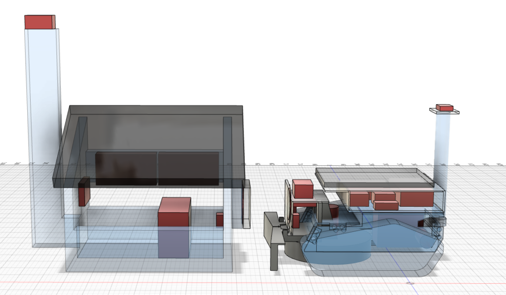
Updated CAD drawing to show both mower and docking station layout.
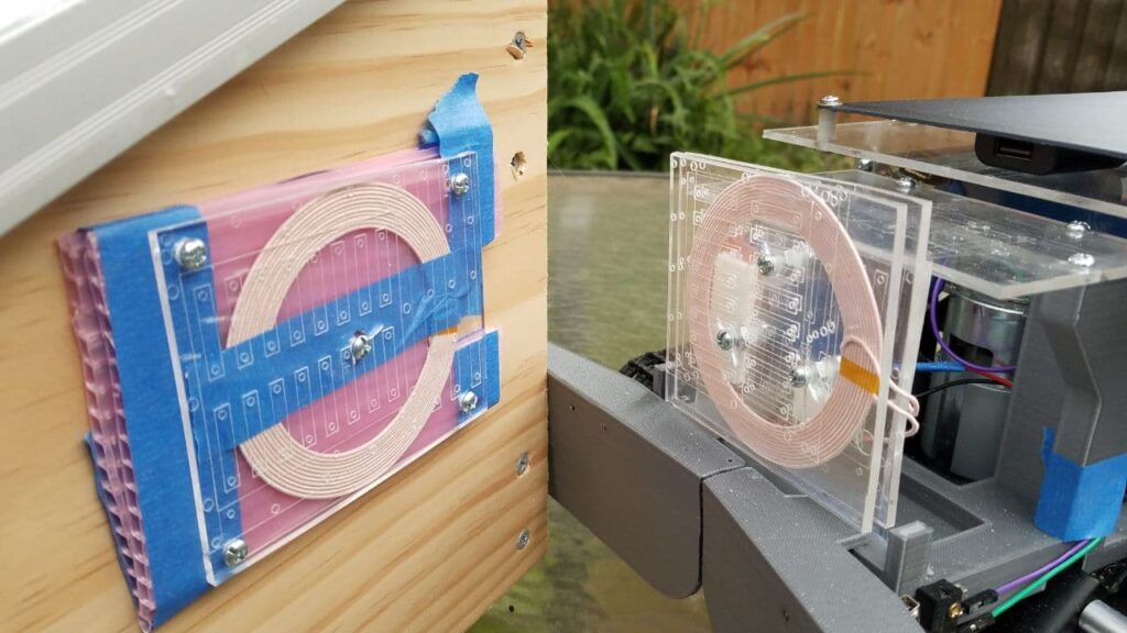
Updated the inductive charge booster and did secondary tests. Original test showed that we can get up to 0.6A of power from the original 12V input 5V 1A out inductive coils, but the engagement distances were very close. Prof Notash suggested finding one with a longer range. After finding another system that can transmit nearly twice the original unit, we installed a 12-24V input 5V 2A out coil system. After installing, we found that the manufacture failed to note that the provided output specs were only for 24 volt systems, while 12V systems will only receive half the output voltage and distance. We installed voltage boosters but the overall function is still limited.
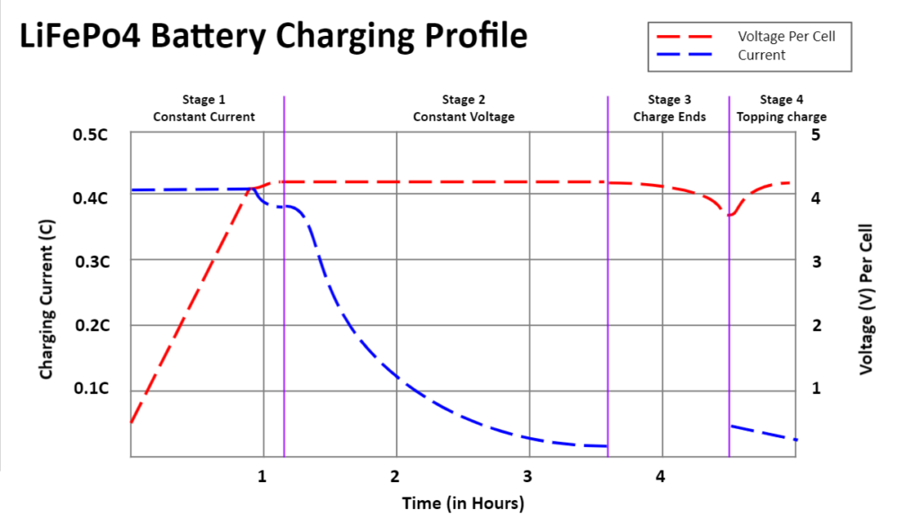
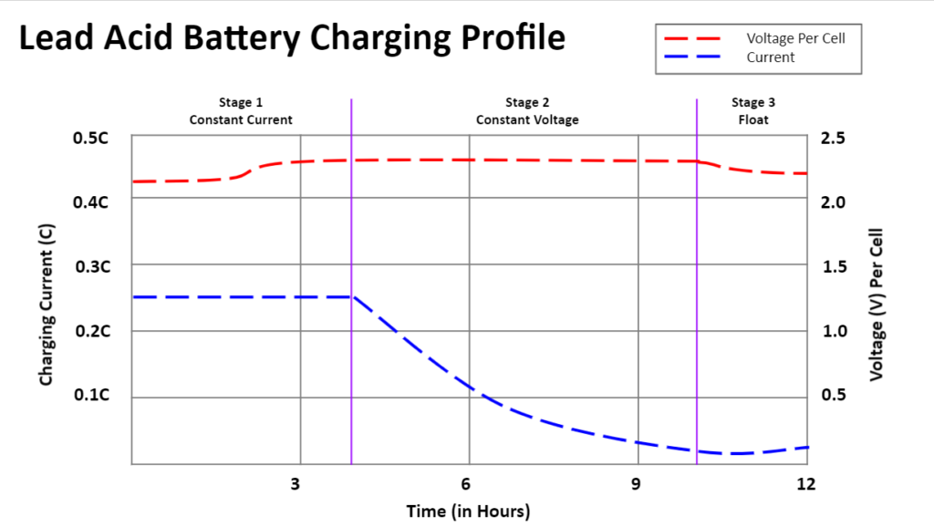
Created several graphics and charts illustrating how each of the battery charge profiles differ.
Applied Loctite to mower screws to prevent screws from vibrating loose while cutter blade is active.
This week all coding for the major components of the mower was finalized. This includes the compass navigation, the GPS border detection, the obstacle avoidance, and the return to home when done cutting.
Fortunately once the GPS has a solid RTK lock, all aspects of the mower are functioning as expected as seen in the videos below.
Unfortunately the reliability of the GPS leaves a bit to be desired. There are times when the GPS will be functioning fine at one point and then a few seconds later the RTK signal drops and the accuracy suddenly plummets. As shown in the videos below.
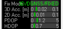
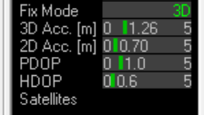
GPS accuracy issues can be caused by several factors. One is not having enough satellites in a given area, At least 4 satellites are needed to be in line of sight of the target to give the roughest estimation of position, in general 7 to 8 satellites are recommended to display a location between 10-11 yards. Satellite position also plays a big role in accuracy, in general having satellites dispersed over a larger area of the sky returns more precise location results. Another big concern is signal obstruction. The GPS requires a clear view of the sky in order to operate correctly, this can be affected by buildings, trees, and human bodies amongst other things. The Ardusimple website which provides the RTK’s actually recommends placing the base station on the roof of the house if possible to provide a more unobstructed view of the sky. It has also been noted that GPS accuracy tends to improve at night. Research into this showed that this happens because there are less ionospheric disturbances when compared to day time. In general a GPS will function better at night and with clear weather.
Week 9, June 27th – July 3rd:
This week, we finished construction on the mower with all components and options integrated, upgraded the cutter blade H-Bridge, upgraded the front bumper sensor flaps to larger setup, integrated inductive charge system from the docking station to the mower, as well as continued to work on code for the GPS and compass.
First the original L298N H-bridge was found to be inadequate to operate the cutter blade as the h-bridge has a max current output of 2A. We mistakenly took the 1.2A no load current for the actual operational current of the cutter motor. However the actual current draw under load testing and attempting to stall the blade at 7.5V was 5A-6A during typical load conditions while cutting grass and upwards of 7.5A while attempting to stall the blade with sticks.
We are now using the VNH5019 which can handle a constant 12A load and upgraded the voltage regulator supplying the 6.5V required to achieve 5,000 rpms to handle 10A. We applied heatsinks as a precaution to protect the components from overheating.

We also upgraded the front bumper sensors we originally installed to allow for a wider sensing area as well as installed the inductive coil charge receiver.
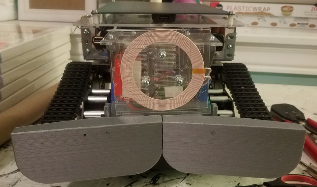
The inductive charge system is designed to utilize a 12v power supply and mimic the solar panel output going to the solar charge controller. As our docking station is using a 12 volt power source, we had to use a voltage regulator to increase the output voltage from 5V to 13V to match our solar panel output. Ideally, we would have wanted to use a 24V power source, but that will be added to the future improvements section. We could have used the voltage regulator to boost the voltage but that would have increased the standby current used.

When using these inductive charge systems, you can’t bring the two coils too close together or the system may pull too much current and burn out the supply circuit, as is what happened during testing. The system we are using can’t be any closer than 15mm, however while we were testing the distances and current draw the coils must have been around 5mm away from each other and the current draw was too much for the supply board and it burnt out.
We were still able to test some current draws from the supply board and received from the charge controller at the 15mm distance. The standby current from the supply board without transferring power to the receiver coils is 68mA, while transferring power with 13V output (using the voltage regulator) and no load is 120mA, and finally while attached to the charge controller as a load 950mA.
The actual current received to the charge controller is only 100mA, which makes this a very inefficient system. Power losses in inductive charge systems is expected but is a tradeoff for a contactless charge system. This is actually amplified due to the voltage regulator.
Due to the current weather and potential hurricane threatening to make landfall this upcoming week, we had to devise a way to test the solar charging system and simulate sunlight conditions for power cycle tests. We ended up utilizing a 500W halogen work light to simulate sunlight. The results were similar to typical sunlight conditions as the sun moves across a cloudless sky.
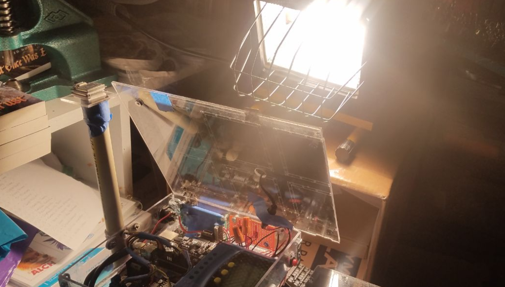

We also took advantage of the non-ideal sun conditions to test charging conditions during the rainy conditions. On average we were seeing power drain around 2 days on a half charge.
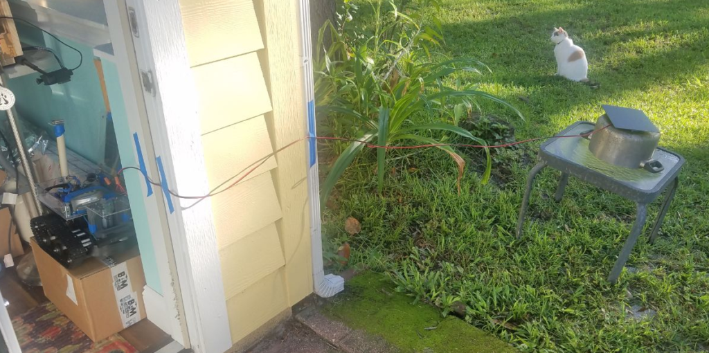
We also finished the initial schematics for the mower, docking station, and controller which can be found here:
https://palmmower.com/senior-design-project/schematics/
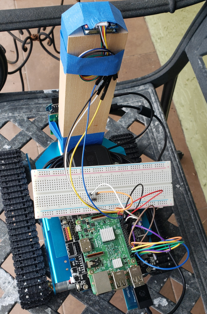
This temporary setup for the test obstacle sensor involves using a simple switch to trigger the obstacle sensor variable in the code. Once the mower detects an obstacle it will move backwards to acquire some distance between the obstacle in order to try moving forward again. If the mower is unable to move forward then it will attempt to maneuver around the obstacle. The mower will keep turning slightly to the side and then attempting to move forward. After the mower has moved sideways enough that the obstacle is no longer in its way, the mower will simply continue the cutting path where it left off.
Week 8, June 20th – June 26th:
This week the group met to work on the mower’s compass navigation and pathing. Due to the fact that the turn angles need to be accurate, it was necessary to limit the turn speed of the mower to avoid overshooting the desired angle. The mower is able to detect its current position in relation to the correct angle and adjust itself accordingly in order to begin moving forward. The mower will only move forward once it detects that it’s facing the correct angle. Now the mower can use the compass to orient itself correctly while relying on the GPS to control how far it should move.
Installed the first draft of the bumper sensors and GNSS antenna holder. The front switch flaps will be enlarged to cover more area now that the prelim design is finished.

Continuing to improve the wiring as the designs become more finalized. Using tape to create a wire harness and help protect the wires from heat generated by the heatsinks.

Replaced the original solar charge controller with a different variant that provides more real time feedback like current charged/used, battery level indicator, power from the panels, and temperature all while maintaining the same features as the original unit.

Did a 30 minute long run test to see how long the mower battery lasts while under constant movement without the cutter blade. Final verdict was the mower can continue to move for over 30 min of continuous use with almost no noticeable drain on the battery.
We did encounter one major problem. During testing conditions, we found that the L298N H-Bridge that controls the cutter blade does not supply enough current to operate the 775 motor at startup and during cutting. This is causing the cutter blade to not come up to full speed quickly and maintain speed while in use.
The 775 motor we are using for the cutter blade is rated to 1.2A but that is with no load and not at startup. We are discovering after further research (not supplied by the original seller) that the required current load is greater at startup conditions and under load.
Originally, we thought the L298N (rated to 2A and can handle spikes up to 3A) will be adequate if we used the second board to just power the cutter blade. However, with these power spikes and learning more about how these motors function we are seeing that more power will be needed to drive the cutter blade as intended. These power spikes could be as great as 10A and the L298N just won’t be able to handle the power running through it.
After researching, we found a suitable replacement that not only exceeds the power requirements needed by the motor but supplies a much larger heatsink. The BTS7960B can handle 5V – 27V input, drive up to 43A, and has the same control inputs that makes it fully compatible with the Raspberry Pi I/O pins. We feel confident after looking into this part that it should be able to handle operating the cutter blade during extended periods and not damage the system and are awaiting approval from Prof Notash.
We are also doing comparison charging tests for both the 10W panel (as originally designed) and a 20W system (2 of the same panels) to test the charge time difference. With 1 panel, we are seeing about 0.15A in direct sunlight, but with 2 we are seeing about 0.3A in direct sunlight. Using 2 panels may help decrease charging time for the first step of constant current applied to the system, more research is needed to verify the difference.
We started putting together supporting documents for the PALM system, starting with the mower schematics, which can be found here: https://palmmower.com/senior-design-project/schematics/
Week 7, June 13th – June 19th:
This week was focused on finishing construction on the electronics housing, app controller development, integration of power control modules, and GPS/Compass controlls.
The Electronics housing was finished with the lid and solar panel installed directly on top. Unit opens like a lid and has a latch to keep it closed.

After spending a couple days researching and learning how to build apps and GUIs for controller interfaces, we settled on two potential options, BlueDot and creating a custom GUI within the Python code. Another option, MIT AI2 App builder, was considered an after a few days of research and testing determined it to not be a viable platform.
Bluedot is the easiest app to set up as it works on your phone, but lacks labels and displays, making it less intuitive. It is still a very viable platform, especially for testing purposes, and may be considered for future use.
The best option is creating a custom GUI for the raspberry pi and is able to be made within python coding. Research for this option is still ongoing but shows the most promise so far. This will allow a user to have labeled buttons and potential output results that may be needed for programing GPS coordinates.

Since the H-Bridges and Witty Pi are now controlling all voltage regulation for motors and power supply, we removed the step down voltage regulators used to power the system. We also added in a voltage display on the outside so we can have real time power feedback while testing.


As originally planned, we are going to use momentary switches to act in as impact sensors in the event that the mower runs across an object while running. We were uncertain about the ultrasonic sensors sensitivity in the event that grass height will give false readings. This is currently being designed this week and should be printed by the following week.
We made a simple bumper sensor, in order to cut down on costs and speed up time for 3d printing, the bumpers will sit high with no skirt going down. we also made a platform to hold the GPS unit above the cutter blade to both provide accurate cuts and offset the weight distribution.

Week 6, June 6th – June 12th:
This week we focused more on GPS navigation, wireless control via phone app, and solar charge testing.
Starting off, we really needed a way to manually control the mower via phone app or remote device. To start doing this we utilized a popular phone app, BlueDot. This app allows us to customize and configure the touch screen interface to have different buttons and outputs to allow for more functionality.
After creating the code, we did a full movement test to verify function of the system.
In the next weeks, wee will tweak the code and app to provide more functionality like cutter blade on/off and programming mode. We also want to verify the voltage output for the h-bridges for documentation purposes and ensure that we are getting expected values.
Next, we performed a battery drain test and charge test. For the drain test, the mower unit was powered completely on and left out overnight. The hope was to see if the unit could last overnight and was starting at 12.7V. When the unit was checked in the morning, the battery was fully drained and needed to be charged.
After doing more research, we found that the Raspberry Pi 3 will have a maximum of 14 hours run time for just the unit on its own with the 12v, 6ah designated for the mower. This is with the Rasberry Pi on standby and not running any programs.
With more research, we found that the Raspberry Pi does not come standard with a proper low power mode or a real time clock which is mandatory for us since we are using a solar powered system and it will operate on a timer. These two functions were left out of the design of the Raspberry Pi to allow for a more affordable price, but without these functionalities, we wont be able to allow the system to be an automated system.
To resolve this issue, we found two viable options; the Sleepy Pi and the Witty Pi. Both of these are low power micro controllers with built in power control and real time clock. They just attach to the headers of the Pi and will power the Pi on and off at whatever time intervals we need. Due to availability, we purchased two of the Witty Pis for our mower unit and docking station.
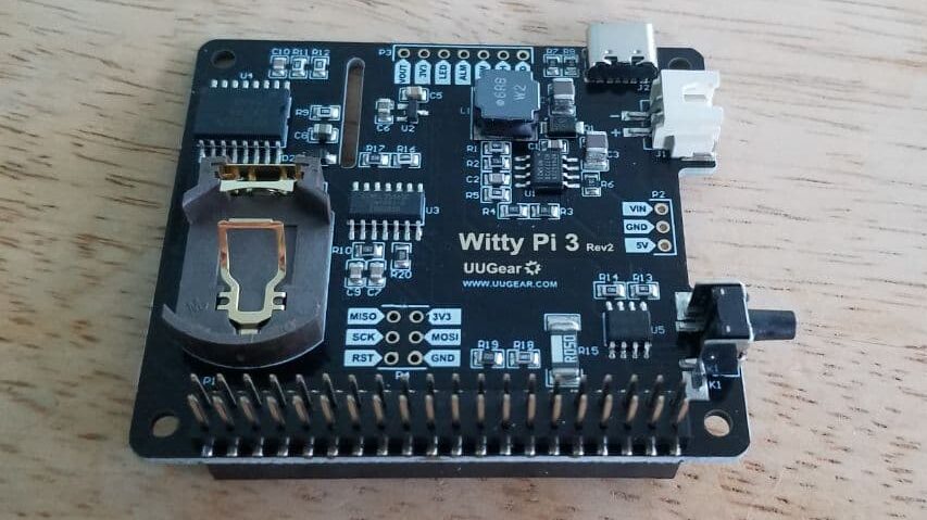
Utilizing these boards will greatly increase our battery life and allow the system to charge after running the motors and performing the mowers tasks without having to worry about the system draining while on standby. Plus the Witty Pi only consumes 1mA so it isn’t a burden on the system.
During the charge test, we found that we could install two of the 10W solar panels on the system since we had done an expansion modification to the mower, providing it with an extra 2 inches of width. This allows us to charge the system faster and can let us to mount one of the panels at an angle to provide two different surfaces to attempt to get the best light angle from.
Since the battery was dead (below 10v for 12v batteries), we had to bypass the solar charger controller and hook up the panel directly to the battery. In the future, this will be unnecessary as the solar charger controller is now set to prevent a dead battery state. This took about a day to provide enough power to the battery with one 10w solar panel. By days end, we had 10.4 v of power reading on the meter.
We then transitioned to the 20W solar system for the first 2 days but then attached an additional 10w panel (30w total, temporary setup) for the last 2 days to boost the charging system and allow us to do more testing with a charged battery. We are anticipating the 20w system on the mower to provide a full charge from a dead battery to full charge in 5 days time. However, we don’t anticipate the system needing to be charged so much during actual run time conditions.
Tested the base/rover configuration of the RTK’s. The modules require line of sight with each other in order to maintain an RTK connection. Tested whether the RTK connection could be maintained through a wall, but it proved unsuccessful. Tested the time required to establish an RTK connection after being powered on. The time to connect varied but across multiple tests the maximum time to connect was about 6 minutes. Giving the mower a few minutes to acquire an RTK lock before moving will be implemented into the code. Tested the accuracy of the RTKs once in RTK mode, and the GPS coordinates were much more stable when compared to the rover on its own.
Programmed the compass to work with the raspberry pi. Initial results seem pretty stable, which should allow for proper steering and alignment of the mower. More real world tests need to be performed to see if the compass requires further calibration.
Week 5, May 30th – June 5th:
This week we were focusing on getting initial drive movement with the mower unit and working on RTK controls.
While finishing up and starting the Raspberry Pi for the first time, there were power supply issues that prevented the system from starting up. Originally, we were going to use the USB ports on the solar charge controller to provide power to the Raspberry Pi, but found that there just wasn’t enough current being supplied to fully operate the system.
After doing further research, we found that the Raspberry Pi requires a higher current input than the USB ports or most phone charging systems can supply. This caused us to utilize one of the voltage regulators to provide power to the system. We set the output voltage to 5.1v and attempted to boot the power.
We started getting another power error, essentially we were getting the right voltage but due to the jumper wires we were using to test the units function were too small and couldn’t push enough current through to run the system. We then changed to a larger gauge wire and soldered directly to the power pins to eliminate power losses from a mechanical connection.
We created a simple movement control code to test the system and power function both in and out of the grass. The current drive motors are capable of moving the mower swiftly through the grass and allows for turning on the spot. Code can be seen below:
Preliminary movement control code snippet.
#-*- coding:UTF-8 -*-
import RPi.GPIO as GPIO
import time

#Definition of  motor pin
IN1 = 20
IN2 = 21
IN3 = 19
IN4 = 26
ENA = 16
ENB = 13

#Set the GPIO port to BCM encoding mode
GPIO.setmode(GPIO.BCM)

#Ignore warning information
GPIO.setwarnings(False)

#Motor pin initialization operation

global pwm_ENA
global pwm_ENB
global delaytime
GPIO.setup(ENA,GPIO.OUT,initial=GPIO.HIGH)
GPIO.setup(IN1,GPIO.OUT,initial=GPIO.LOW)
GPIO.setup(IN2,GPIO.OUT,initial=GPIO.LOW)
GPIO.setup(ENB,GPIO.OUT,initial=GPIO.HIGH)
GPIO.setup(IN3,GPIO.OUT,initial=GPIO.LOW)
GPIO.setup(IN4,GPIO.OUT,initial=GPIO.LOW)
#Set the PWM pin and frequency is 2000hz
pwm_ENA = GPIO.PWM(ENA, 1000)
pwm_ENB = GPIO.PWM(ENB, 1000)
pwm_ENA.start(0)
pwm_ENB.start(0)
Video of movement tests:
While testing, the original power button started to fail. This may have been from overheating due to soldering but before any further testing can be done a new button needs to be installed for safety concerns.
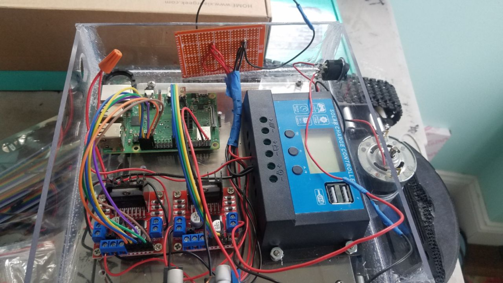
We also created a board to connect and manage the power lines. Originally, all the power lines were coming directly out of the solar charger and were mechanically connected with the terminal block. Instead of opening and closing the terminal block for troubleshooting, we made a rudimentary wire organizer with a perf board. This allowed for better wire management and troubleshooting.
This week there was a heavy focus on working with the GPS functions of the mower. Once the GPS data was being transmitted to the Raspberry Pi this allowed for multiple tests to be performed. The first test seen below is a GPS accuracy test where the RTK is held in a box while giving instructions to the user regarding which direction they need to move in to reach a predetermined waypoint.
The next test was meant to try out the mower’s response to the GPS signal. The setup was simple, the mower would only begin running once it was inline with the GPS waypoint. If the mower was not aligned with the waypoint the tracks would stop moving and wait for the correct alignment.
The final test was to place the mower on the ground while the GPS was held behind it to see if it would move and stop accurately according to the GPS position.
Week 4, May 23rd – 29th:
This weeks meeting with Prof. Notash was quick and we updated him on our progress and talked about implementation of some of the suggestions from the industry experts (primarily kill switches). To view the presentation, you can download the PDF below:
This week we focused on getting the primary mower unit wired and all components troubleshot and installed as well as learning more about how the RTK boards work.
The mower electronics are now mostly installed and when completed should be able to provide basic movement controls. We still need to wire the h-bridges to control the driver motors and add coding to the unit for a full moment test.
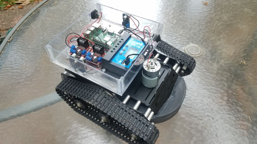
The unit currently has two power switches, one main power switch in the back that controls power to the entire system from the primary 12V power supply, as well as a power switch just for the cutter blade itself. The cutter switch will allow us to fully test the unit and provide a safer test environment.
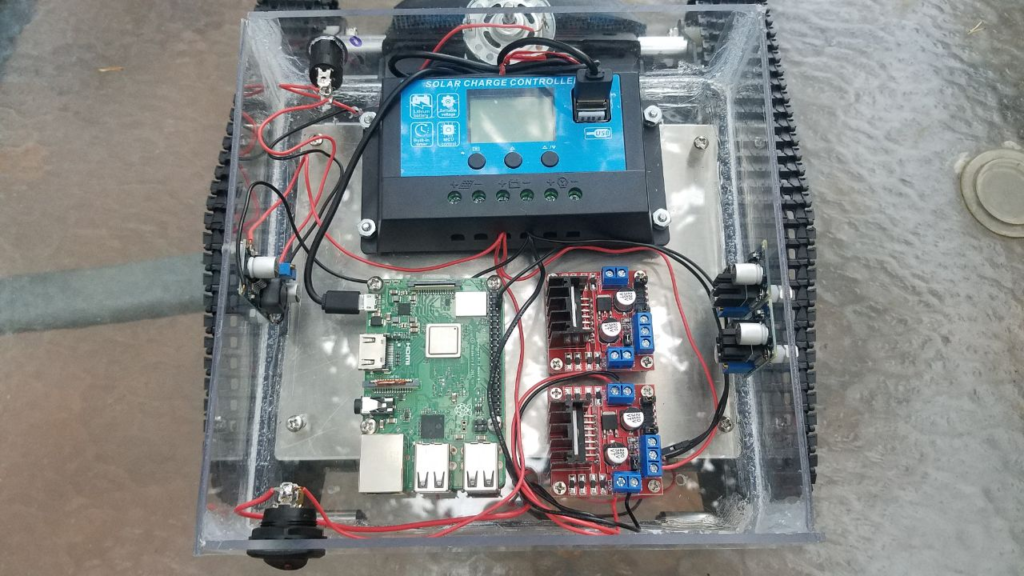
The electronics inside the unit are the solar charge controller, the Raspberry Pi, two h-bridge stepper controllers, and voltage regulators.
The Raspberry Pi will be the heart of the mower and will control the majority of the system. The L298N h-bridges will control the motors themselves. One h-bridge will control the drive motors and the other will control the cutting blade. Originally, we thought we may need more voltage regulators, but we learned that the h-bridges we purchased can be voltage controlled as well, thus acting in as a voltage regulator. We will keep the voltage regulators on hand and remove them if they aren’t being used.
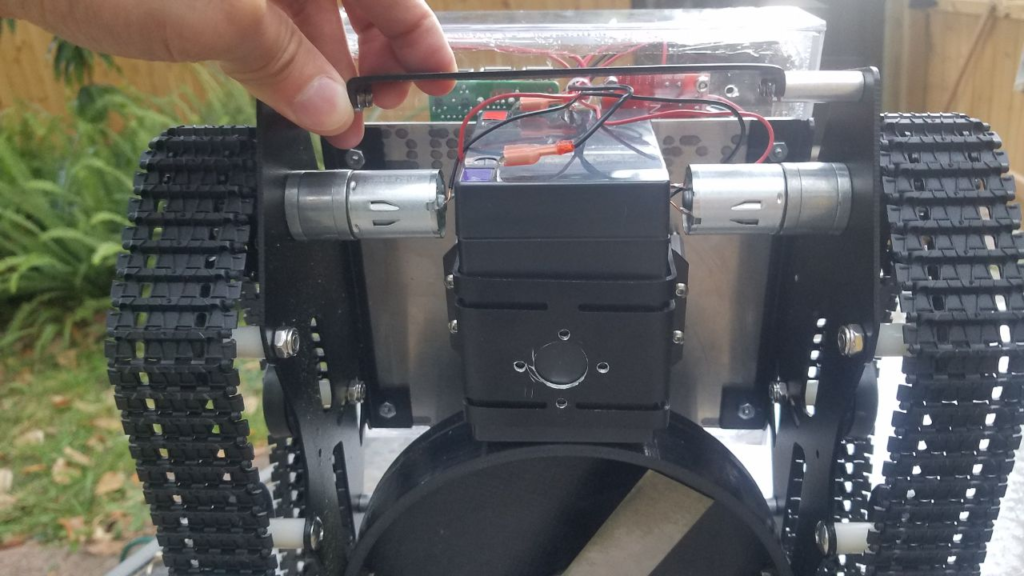
We secured the battery to the bottom of the chassis by using a clamping style bracket to hold it in place. This holds the unit up high enough to clear the ground and provides some protection from impact.
The original wires that came with the drive motors were lower quality and a very small gauge that was easily broken (tugging on them broke the wire). We replaced them with solid copper wire and soldered them in place.
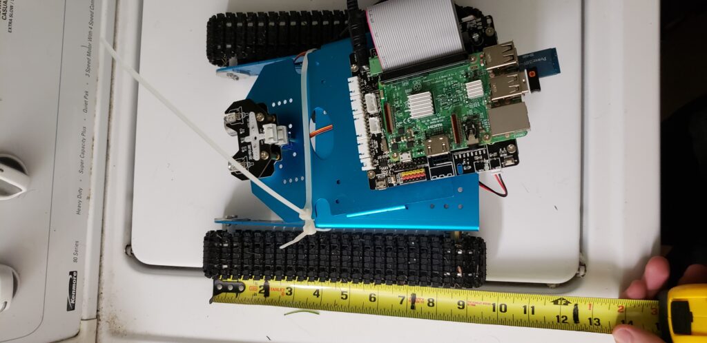
Demo unit was measured to be 9.5 inches by 9 inches. Significantly smaller and lighter than the full sized unit.
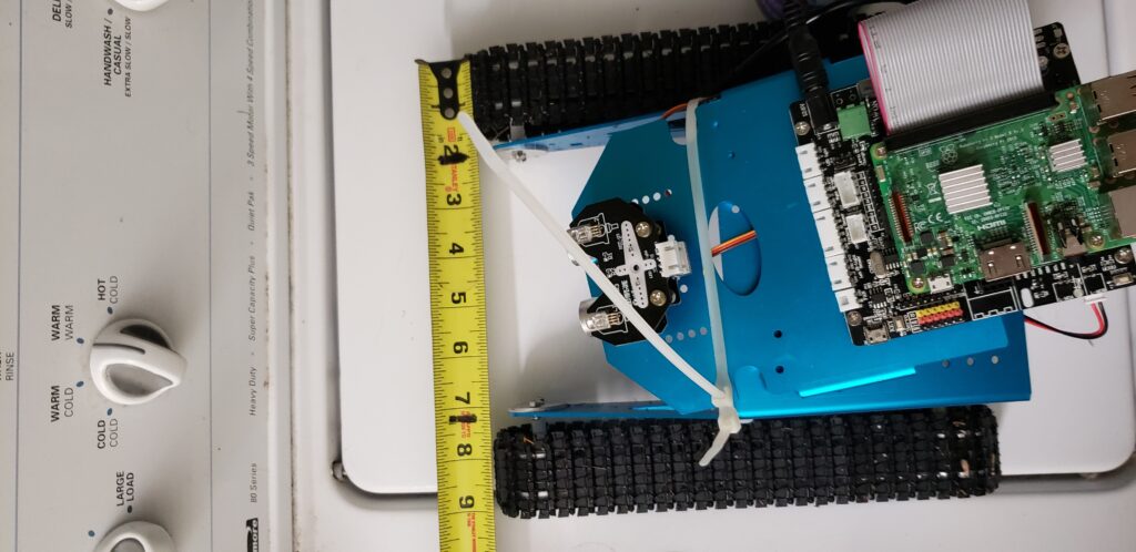
Created two cutting path demos using python. One path uses a spiral motion which starts on the outside of the barrier and makes its way inside while tracing the shape. The second path option uses a zigzag motion to go up and down the lawn until it reaches the other side and then returns to home.
Researched the motor coding for the mower and discovered how to determine mower speed. This video shows a demo where the mower starts at a higher speed and then slows down. This speed can be easily adjusted by changing a single value in the code, but further research is required to determine the maximum speed that won’t damage the motors.
Tested the mower on grass and the default speed had issues successfully propelling the mower through the grass.
The speed was increased by 50% and the results were significantly more promising. It is also possible that by further increasing the speed in the code the mower could navigate the grass successfully but we do run the risk of overexerting the motors. That being said this unit’s purpose is more for demonstration so these issues might not be present in the full unit. The full unit possesses significantly larger tracks and stronger motors, and the demo unit was able to maneuver in grass with a speed boost. For now the full unit would have to be tested but its performance is expected to be satisfactory.
Week 3, May 16th – 22nd:
In our second meeting with Prof. Notash we provided updates and details on building the docking station and RTK integration as outlined in the previous weeks update. To view the presentation, you can download the PDF below:
In our meeting we discussed the addition of adding the ability for the docking station to charge the mower while on standby. This was an idea we as a group entertained during the proposal phase but put off to the side as an optional feature if time and budget allows. The idea was to use an inductive charging system and have the docking station act like a garage where the mower can sit underneath the docking station with the inductive coil receiving power sit just underneath the mowers solar panel and interface with the supply coil inside the docking station.
Again, this idea is marked to be optional and will be implemented if time and budget allow.
We also discussed updating our flowchart and block diagram to integrate the safety measures the industry experts suggested (kill switches and safety switches) as well as the optional charging interface. New layouts can be viewed in the following link: https://palmmower.com/senior-design-project/block-diagram/
The cutter blade shroud was installed, but we had to do some slight modifications due to minor changes to the positioning of the cutter blade. Originally the blade was just a little too far up so we had to find a way to adjust the blade height, resulting in us needing to remove some material on the top of the shroud to fit around the exsisting metal. The shroud is secure and will make the overall design safer to test when the blade is installed.
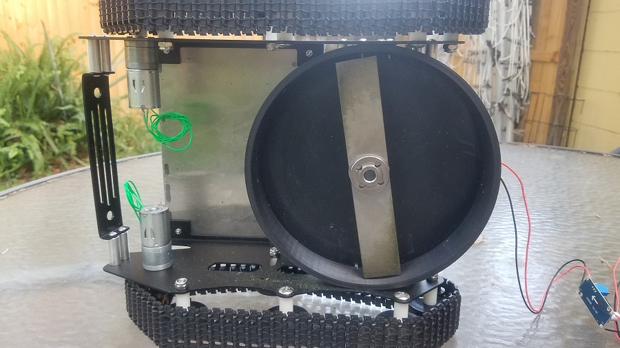
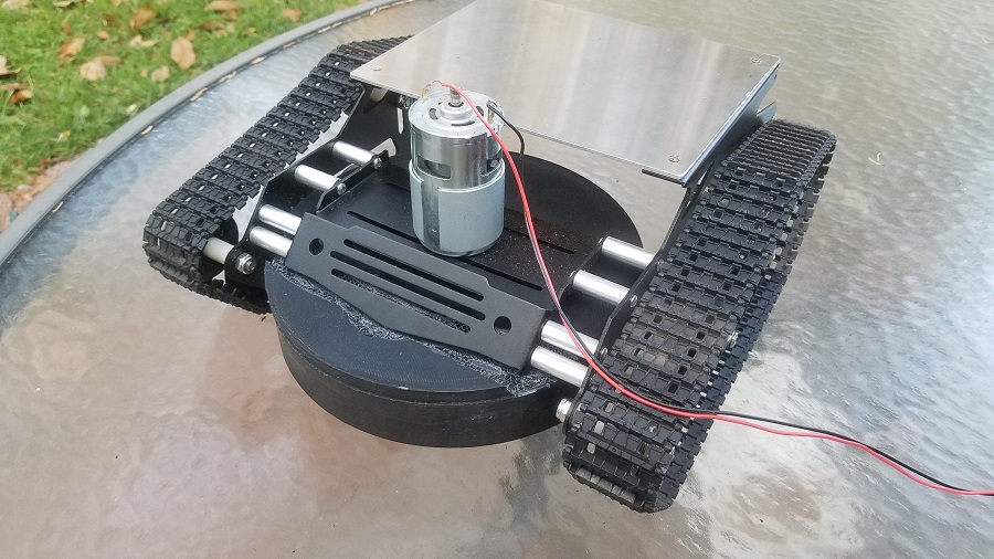
We also started assembling the electronics enclosure that will hold all major electronic devices. It is made of plexiglass and measures 8″ x 8″ x 2″ and secured in place using RTV adhesive to ensure a water tight seal. The carrier will be secured to the mower chassis with screws and standoffs.

Next steps for the mower is to start securing hardware in an initial configuration for movement testing as well as continuing developing and testing movement code.
Implemented coding for mower movement. The mower is able to move forward, backwards, and turn in place towards either direction. For now the code is using an if-else statement inside a while loop. Each of the four directions are waiting for a specific value to be triggered. Once the rtk system is active we can simply change the the conditions of the if-else statement to work with the gps information from the rtk.
Week 2, May 9th – 15th:
This was the first week of the summer semester that we had a meeting with our project adviser, Prof. Notash. We provided a quick recap of where we are at and what our next goals are. To view the presentation, you can download the PDF below:
This week we are starting to program and code basic remote controls to the mower by using Bluetooth connectivity with the Raspberry Pi and a simple phone app we will design for initial testing. This will allow us to verify basic drive functions are working on the mower before moving to automated movement via GPS.
We also got together to exchange components that the other person will need in order to test and program with. Gabe was given the RTK units, antennas, and two step down voltage regulators with heatsinks. Brian was given a Raspberry Pi and SD memory card.
We are currently developing code to allow us to test basic movement functions and have done research on integrating the RTK units with the Raspberry Pi, as well as what programs will be needed. According to Ardusimple, who made the simpleRTK2B devices we will be using, we will need 3 programs: SDFormatter, Win32DiskImager, and PuttY.
SDFormatter will allow us to format and set up the SD card with the appropriate operating system to drive the Raspberry Pi, and Win32DiskImager will write the OS on to the SD card. PuttY is a free Secure Shell Protocol (SSP) and telnet client that will be used for RTK communication.
We also built the docking station that will be used as the housing and power station for our stationary RTK unit. This station will be self sufficient with its own solar power recharging system and allow for the mower to receive real time corrections while moving, providing us with the accurate positioning we need.

The device measures 320mm (12.5″) Tall and 395mm (15.5″) wide and is using a Mighty Max 10W Polycrystalline Solar Panel angled at 28*, Mighty Max 12V 9Ah Rechargeable SLA Battery, Gdcreestar Solar Charge Controller, and will have a Raspberry Pi and simpleRTK2B unit installed once initial product testing is complete.
The angle of 28 degrees was chosen for the solar panel as it is the best average angle for year round solar panel efficiency. The unit will eventually be sealed from rain with plexyglass once all electronics are fully tested and deemed operational.
We also received feedback from an industry engineer providing us with ideas and feedback on how to proceed safely in regards to the cutting blade (ie kill switches), possibly needing a battery backup to prevent OS corruptions during power fluctuations, and ensuring we have the correct data transfer rate and no latency to prevent us from cutting over a boundary.
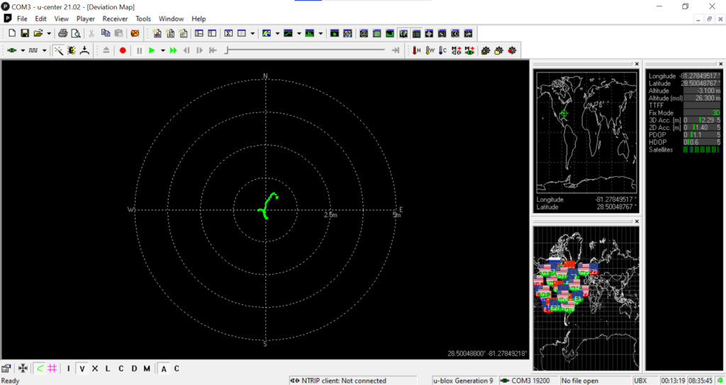
U-center software allows real time tracking of the rtk. A quick test was performed to test the accuracy of the longitude and latitude as well as the accuracy of the movement tracking.
The software was able to detect a circular like movement from the rtk. This test was performed indoors and using only one rtk unit. The accuracy of the system is expected to be higher when used outdoors and once two rtk’s are setup to work together as a base and a rover.
Week 1, May 2th – 8th:
This week we went over what we believe the next steps are for our project and have decided to get the drive system up and running first. We will begin with having remote control functionality with our smartphones and connect to the Raspberry Pi via Bluetooth to verify movement functions.
We received in the RTK boards we will be using for the base station and the mower itself. To make things easier to integrate, we used an adapter board to connect the simpleRTK2B to the Paspberry Pi and soldered the necessary headers to the simpleRTK2B.

After ordering in a tachometer, we fine tuned the 775 motor have an input voltage of 5.9v giving our cutter blade a rotational speed of 5k RPMs. We felt that this will be our targeted cutting speed and minor tests showed that it will cut the grass with ease. Faster speeds can be looked into later but the blade will need to be fine tuned for balance as there are vibrations induced at above 6.5k RPMs.
Due to COVID, we are having to work remotely and need a similar test bed available to each of us to fine tune control functions. For this, we have a secondary test mower without the cutter blade installed that will be used to test coding and components remotely.
